Sales Message Goes Here
E-GO Models SU27 Flanker power system installThese are the basic instructions for removing the old fan assemblies and modifying the airframe to suit the new battery, ESC's and EDF64 fan units.
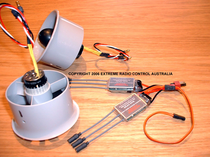
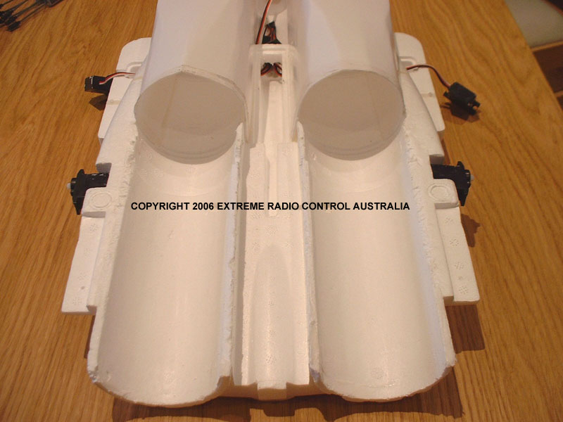
Click on the pictures to enlarge them. POWER SYSTEM AS SUPPLIED BY US READY FOR INSTALL1. Remove the elevator servos (you will need to remove the vertical fins first if your plane is assembled) this allows you better access to slicing the lower molded half of the exhaust tube off. 2. Remove the white tape stuck over the join where the fans are mounted. 3. Using a new flat blade, slice through the glue joints on both sides of the fan housing, all the way down to the black plastic exhaust tip. Carefully lift these up and slice through the silicon still remaining as you lift. Once the entire foam shell is free, you can gently pull the plastic exhaust tip off backwards, starting at one side and taking your time. The white silicon will give if you apply slow even pressure, you will then end up with the half shell and the black exhaust nozzle still in one piece. 4. Clean the silicon from the foam of the fuselage, and then carefully pull the fan unit out. It has double sided tape all around and is quite easy to separate as long as slow even pressure is used. 5. Cut the wires where they join into one, and pull the fans out of the airframe. You will then end up with a clean airframe as seen below.
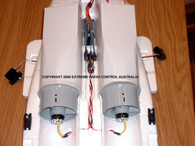
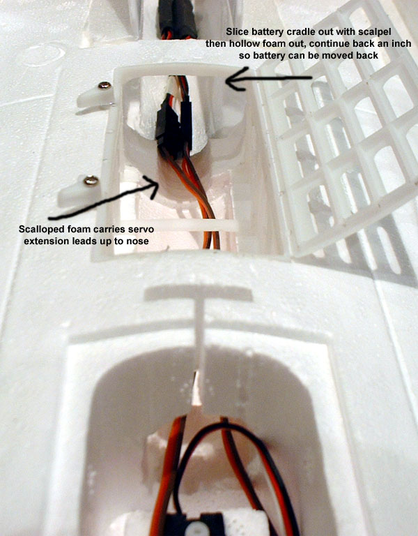
6. Once the airframe is clean as in the above photo, you can feed the fan wires through the existing wiring port, one at a time, this will stop any widening or damage to the foam track. 7. Gently pull the wiring through as you line up the fan in the groove of the foam, we need to use double sided tape right round the fan housing so as to close the small gap (the EDF64 is a tiny bit smaller in OD to the old EGO fan housing) you should end up with your motors sitting exactly as shown in the pics below, with the wiring running neatly into the first compartment. 8. Next is to stick the fan housings into place using the supplied two rows of 1mm thick, 12mm wide double sided tape. Once this is done you can glue the exhaust ducts back on, I use polyurethane glue such as Vise Grip from Bunnings, epoxy can also be used but is heavier and harder to trim and clean up. 9. White cloth tape is used to seal the front and rear ducts around the fans where we removed the old paper tape. I tried electrical tape but it peeled off after a few hours. 10. Cut out the rear of the battery cradle as shown in the photo below, then using a soldering iron first open out the foam towards the rear of the plane, once the major foam is out you can use a Dremel with cable attachment and grinding stone to clean up the foam and create a nice tunnel for the battery. Now may be the time to buy a Dremel or Arlec rotary tool! 11. At the base of the battery tunnel cut a channel to carry the cable for the front wheel servo. 12. Open out the bulkhead between the compartment behind the battery and the motor wiring channel, this will make it much easier to fit different size receivers in the space behind the battery. 13. Cut a balsa hatch that covers the length of the wiring compartment, from the rear section up to the rear of the Receiver compartment. On the underside of the large fixed hatch, glue small balsa squares across the grain to strengthen the hatch panel. Leave a scalloped hole at the rear of the large fixed hatch for the motor wiring to come up through, we will be placing the speed controllers on the outside of this balsa hatch between the motor nacelles. 14. Epoxy the rear hatch piece into place, this forms the lateral strength of the fuselage between the air intact ducts, and removes a lot of the flex between the motor sections.
15. I put heat shrink around the Y lead plugs, pair up each Y lead and shrink over each pair as one, it removes any risk of a plug coming undone and neatens up the wiring. Be VERY careful shrinking in the confines of the fuselage, heat causes foam to blister badly! 16. Your receiver will sit behind the battery in the large area and your aerial should run out of the side of the fuselage underneath the wing and along the length of the wing. Tape the aerial to the wing all the way out to the tip. 17. You can then make a second hatch to cover the receiver compartment, use a tongue at the rear edge to lock the hatch under the rear balsa hatch, a screw or magnets can be used at the battery end to secure the hatch. This hatch will be your access to plugging in the battery, and needs a hole in the rear section of the hatch for the battery wire to protrude. This also aids in airflow to cool the battery. The centre of gravity is shown below, with the tunneled out battery compartment, the battery can be moved up to 2cm back from its forward most position. In tests the Competition battery gives a COG at the original position with a micro receiver of 10 grams. With the slightly heavier Sports battery option the COG is slightly forward of the factory position, this can be adjusted if required with a very small amount of lead at the back of the fuselage. Customers pls email for details on COG OPTIONSOther options are bracing the wings with 0.5mm thick carbon fibre strip pushed into a slit the entire length of the wing. The strip will follow the panel line as seen in the picture above, directly behind the aileron servo. The strip should run the entire length of the wing, and into the wing root as much as possible without disturbing the servo wiring. Epoxy any CF in place with a very light smearing of 5 minute araldite along the length of the CF. Carbon fibre strip can also be used along the inner walls of the fuselage. To do this you would start at the front of the fuselage in the main compartment where the steering servo sits, and push the CF strip through the bulkheads so that it runs along the walls of the compartments from front to back. Sharpening the CF strip aids in piercing the foam. So far though the test flights have shown no issue with strength of the airframe in its stock form. |