Sales Message Goes Here
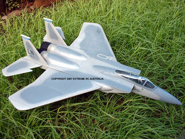
GWS F15 EAGLE EDF JETAnother great jet from GWS, quality of finish and fittings is first rate, this should be another winner!
Exhaust is the standard GWS setup with tapered nozzle, much like previous GWS kits, maybe not as much taper, With a 58mm diameter exit it boasts around 90% FSA (Fan swept area) which should give a good mix of static thrust and speed.
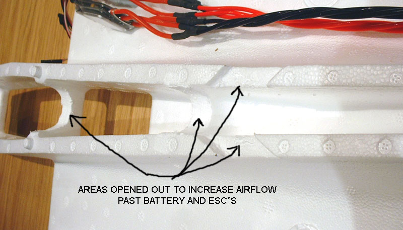
Inlet dimensions are 57mm high and 62mm wide at the entry point, inlet is square. Inlet dimensions are 58mm high and 74mm wide at the leading edge of the cheater holes, this section is round (well oval) and should provide enough flow for the GWS fans. The kit boasts either Elevons or full function controls, and removable clip on wings. I am going to fix the rudder fins permanently as I dont like the messy looks of the screw on bracket system. The more I look at this fuselage the more impressed I am, its mostly very well thought out, about the only thing I could knock is the cooling airflow for battery and ESCs is limited through the front section and needs to be opened out, and there is not much room in the front section period, without burying the ESC's you would have a very cramped space for the receiver, and potentially a lot of noise. Building the kitI started by assembling myself a set of balanced fans, nice and smooth at 35,000rpm when using our Extreme Power EXP2200 4s1p 25c battery pack. I cannot feel any vibration through the housing when running at WOT. Of course when you order a power system from Extreme RC you get fans just like these! I have wired up the ESCs with 16AWG Mil Spec Silver/Teflon wire from ESC to motors, this is a very high spec wire that is equivalent to 14AWG copper. Also very small being PTFE coated, it just fits into the channel for the wiring without modification, always a good thing! The wiring channel really needs to be bigger if you plan to use silicon wire and not the stuff GWS provides. I would also advise scrapping the GWS plugs and hard wiring the motor end, use plugs at the ESC end if you really want to, but if ESC replacement is ever needed you are going to have to cut the plane up regardless whether its got plugs or not.
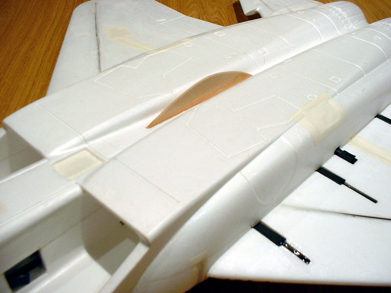
I then opened up the air passages in the front of the fuselage, and cut more exit slots to match the ones already moulded into the inlet duct area. This can be seen in the picture above. I fitted a fan to the fuselage and cut out one of the cheater hole covers to test the theory of the cover not being strong enough to resist the suction from the fan. Well the cover is plenty strong! In fact its quite a decent thickness and fits absolutely perfectly to the foam molding, adding to the clean finish this plane is going to have.
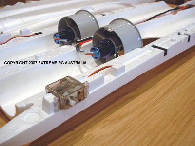
Now the amperage drop in the last test must be from the ESC, E-meter, and everything else warming up, as it was around 15 degrees C during the testing. All in all very good results, this calculates to 550 grams+ per fan in the fuselage with cover in place, no modifications to the cover shape etc. I am very happy with this. With a fresh 25c or 30c battery we should be holding close to 14v if not more, which will give us an extra 3000rpm or so at the fans! One thing to note: the sound of the fan in the duct with the cheater hole open is not as smooth as when the duct is sealed and full length, and you can feel strange vortexes of airflow around the cheater edges when you float your hand around the perimeter. Would be interesting to run smoke through the inlets to see what happens to the air in front of the fan. Definitely I would recommend covering the cheater holes! On with the buildNext up is fitting the servos for the all moving tail surfaces. This is an easy job when the GWS PARK servos are used as the cutouts are made to fit these servos snugly. As you can see in the picture the servos fit neatly into their cutouts.
After the servo work I fitted the wing mount assemblies, this requires epoxy in order to be 100% sure of strength. Very little epoxy is required as the parts are a firm push fit. Wings line up perfectly once fitted. I use GWS glue to fit all the fiberglass braces in the wings and stabs, make sure you pick the right rods and cut the ones for the rear if you are building with all moving stabs. I will fill over the rods with Red Devil Spac-Filla and clean up the joints.
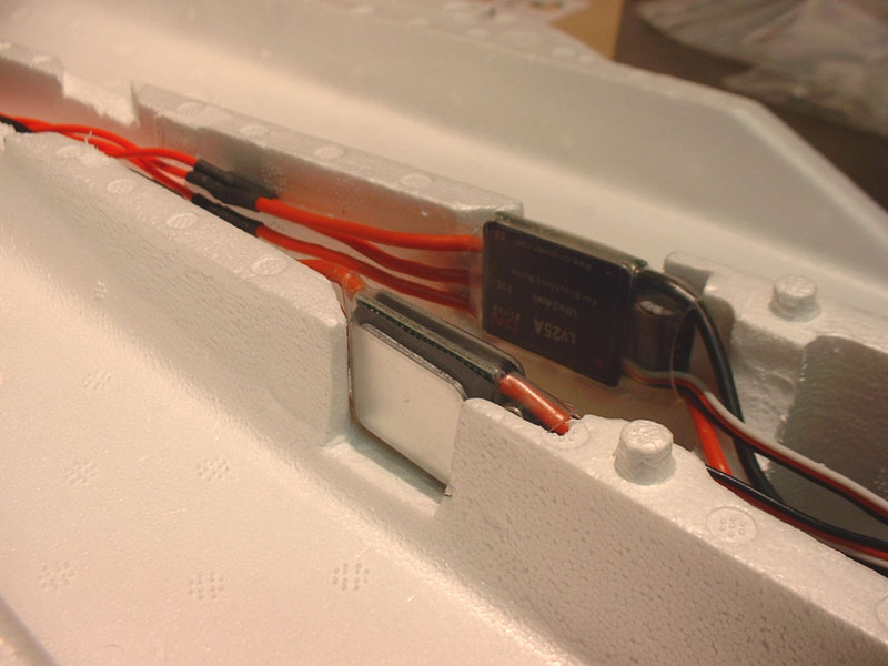
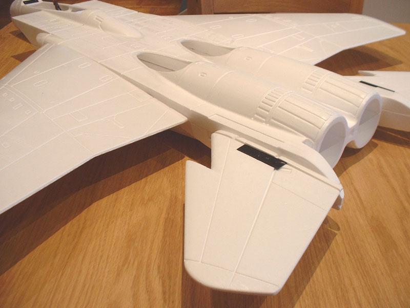
Finally cut out the ESC windows in the front section of the fuse as seen above. BEC is wired in and the new super short Y leads GWS has included in the kit are very welcome, saves a lot of wire stuffed into the small compartment! Final testing has been done before the fuselage is sealed up. Once the battery pack was warmed up it sat around 13.7 volts and 540 watts, everything running smooth as, 39-40 amps total draw inside the fuselage with the cheater covers on. There has been some discussion on the position of the all moving tail surfaces, the standard GWS position has them hanging below the servos which does not look very neat or scale. Flipping the brackets over on the main tail surfaces and repositioning on the servos showed a much cleaner look, all thats needed is the tail sections to be reshaped to more of a point underneath, this helps emulate the real aircrafts looks.
I will not glue the short stabilizer pieces on until the fuselage is together and the elevons are in place, then I can line them up 100%, glue them, then fill all the rod slots and other gaps so as to clean up all these foam pieces that come together at the tail section. I was thinking about the cheater covers and smoothing the underneath, I decided to smoothen out the edges to create a flow of air around the cheater covers and minimize the turbulence as much as possible. Today I glued the fuse together, the method I used as follows: 1. Cover the contact area on both halves with GWS glue, use a finger to make the coverage perfect and remove excess, then let them sit for 15 mins. 2. Sit the fans and wiring in the top half, then pick up one fan housing and silicon all round the outside, refit and rotate back and forth to seat it. Make sure when you fit the fans that the hole in the fan housing points directly at you, which is straight down when the fuselage is together. This will make it possible to access the fan and remove the shaft adaptor and rotor, all you will need to do is remove the cheater cover and then run a hole underneath into the fans access hole for your hex key. 3. I then attached the servo extension leads and taped them down with tiny bits of masking tape so they wouldnt move around while I positioned the bottom half of the fuselage over the top. 4. I then plugged in an Rx and tested the fans again just to be 100% sure I hadnt damaged a wire or anything else, as the motor wires coming out the back of the cans is quite easy to damage if you are rough with it. 5. I then lined up the nose and guide hole at the front and lowered the fuse bottom onto the top, pressure all around the two halves had them glued real good. I taped it around the perimeter while under pressure and left it. 4 hours later and its pretty well set, will take overnight to fully set, but by using the GWS glue as a thin film of contact adhesive you end up with no glue squeezing out all over the place and almost no cleaning up of the seams. Next up I connected the servos, programmed DELTA into the radio and found the right elevon to be way out of alignment! I couldnt get the PARK servo straight, lucky with DELTA you can go into your sub trim programming and trim either aileron or elevator (depending on which one is out) and line the surfaces up perfectly. Took 43 points of sub trim to get it right. Not sure why this happened, GWS servos are usually centered correctly when assembled at the factory. The elevons work perfectly, very stiff with the Park servos, the whole rear end is quite strong. Also looks a lot better with the stabilizers in the up position rather than hanging below the servos, you cannot see the servos, and they line up with the wings much better. The rudder fins are last to be epoxied on, you can use the GWS fittings to make them removable but I chose to glue them on permanently for a cleaner look.
As I do not want to use undercarriage I chose to fit a hand launch fin to hold onto. This is made from 3mm ply and is buried around 3-4mm into a slot cut in the fuselage between the two engine nacelle moldings, and with its centre at the COG point. Size of the ply finger hold is 160mm long and 35mm wide. Curve it in a semi circle shape. Pilot figure chosen is from Wemotec, these Wemotec pilot figures are really detailed and deserve a good paintjob. Final painting was done with Tamiya light grey and neutral grey acrylics with an airbrush, then sealed with a satin UV clear coat. Exhausts are matt black and titanium acrylic also from Tamiya. The end result is a superb looking aircraft!
|
|||||||||||